UREI LA-4 Optical Limiter Expedition
ã 2000, 2001, 2002 & 2003 by Eddie CilettiThe RETRO audio craze has turned everything old into gold. But is this old stuff really so cool? Did we somehow forget how to make great sounding gear? What's the difference between cool old gear and stuff that needs a technology transfusion?
The answer to these questions can be found in the simple investigative process of troubleshooting no matter whether the goal is a repair or an upgrade in this instance, by using a stock UREI LA-4 as an example. The old fashioned optical limiter is nearly foolproof, the added RATIO control makes the LA-4 more versatile than its predecessors the Teletronics LA-2A and LA-3A without the added confusion of Attack and Release controls introduced on "modern" optical limiters. Remember, part of the beauty of OPTOs in general and the LA-2 / LA-3 / LA-4 in particular is their simplicity.
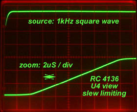
Unlike its respected Tube and discrete Transistor ancestors, the LA-4 uses an early quad opamp called the RC-4136. This op-amp sucks because, as the input level increases the LA-4 becomes quite literally dark sounding. .In geek speak, this is called "slew rate (speed) limiting". With vintage gear, the technician always has an option to "just" fix stuff and leave whatever creates "character" as part of the box OR take the inquisitive approach, "what makes this box work?" Where's the magic and where's the funk? Can I make it better?
It all started out when a minor repair to a UREI 1176 turned into a "subtle improvement tweak." This intrigued the customer enough to bring over a pair of LA-4s (of which he has eight) for similar treatment. To backtrack, I have this technique of using a square wave oscillator to find bad capacitors, the type of component failure that causes loss of low frequencies. (Read this link: Hunt for Bad Capacitors to learn more.) I used the same technique on the 1176, the added benifit fo the square wave technique is that it also reveals high frequency anomalies like transformer ringing. In this case, I found an Impedance Sensitive part of a circuit, realized that one option was to use a jigher grade of shielded cable so as to avoid attenuating high frequencies.
The same approach was applied the LA-4, tracing the signal from each stage, watching it slow down considerably after passing through four op-amps. Figure-1 shows the input stage of the LA-4. Via two amplifiers, U1 and U2, the balanced (differential) input stage eliminates the need for (and the sound of) an input transformer. U3 can be switched for either normal (unity) or high (30dB) gain. It is then followed by a "build-out" resistor R13 that when combined with the photo-resistor, creates a voltage divider / gain manipulator. R13 is a rather high value 82kW large enough so that any "stray" capacitance (from the opto, U4s input and /or the socket and the circuit board layout) also slows the rise-time of the square wave. I am not bandwidth obsessed, its just a troubleshooting technique.

Figure-1: A simplified schematic of the LA-4s front end.