Electric Crayons, Anyone? The Altec 1566A: A Vacuum Tube Microphone Preamp / Direct Box Project
Original ©1996 by Eddie Ciletti for publication in the January97 EQ Most recent update: November 2004
The Essence of Simple, Class-A Vacuum Tube Circuitry

FIGURE-1: Three overlayed oscilloscope traces show clean (green) and "soft" distortion (violet and red) |
vacuum tube evaluation  |
I stumbled upon the Altec 1566 quite by accident and, needing an active Bass DI on short notice, made some quick modifications and received rave response. When the session was over, I took the package back to the lab to refine the mods and do the research that became this article.Figure 1 shows two distortion variations (in red and violet). Notice how the violet wave follows the green wave perfectly during its positive excursion but falls short of the mark during the negative swing. The red wave is more symmetrical, but not "clipped" as would be the case if an IC op-amp were overdriven. Op-amps are visibly clean right up until the point of clipping, this tube circuit is not.
FIND IT OR DO-IT-YOURSELF
Looking to cut your teeth on a simple vacuum tube project? Keep your eyes peeled for an Altec 1566A microphone preamplifier, circa 1958, (see Figure 2). I found two of these single rack-space critters, one at an outdoor religious theater in Eureka Springs, Arkansas and another at Baby Monster Studios in New York City. (Quite a stretch, eh?) The 1566A is a sleeper/dust collector that can be had for less than a song (a verse, perhaps?) and turned into a usable addition to your arsenal of "Electric Crayons" with just a bit of effort.

Resistors Capacitors R1 100k C1 0.047uF / 50 volts R2 1meg C2 50uF / 50 volts R3 1k2 C3 0.15uF / 400volts R4 100k C4 .005uF / 100volts R5 1k2 C5 1.0uF / 250 volts R6 100k R7 47k P1 1meg
Regarding capacitance values, a common rule of thumb is for the max voltage applied to the cap to be 75% of the rated operating voltage. In this case, consider that a solid-state power supply is "instant-on," the raw DC at the head of the supply is going to all caps (until the tubes turn on and lower the voltage).
Relative to what is currently available, remember these are power supply caps with a tolerance that is typically 20%! So, if you can't find exact values even with the audio caps choose the next HIGHER value.
DO IT YOURSELF?
Sure, why not? Youll need a punch tool to make holes into a metal chassis for the tube sockets. Soldering some of the more massive components requires an iron with more power than those used for PCB work. Select a tip thats at least 1/8" to 3/16" wide. Remember to get the work hot enough so that it can melt the solder dont ever "paint" or drop solder, it must flow!
This is not a battery-powered project. Vacuum tubes require two power sources: a low-voltage, high-current supply for the filaments and a high-voltage low-current supply for the plates.
Click here for the power supply schematic and circuit explanation.
THE AUDIO TOUR: Voltage, Current and Impedance
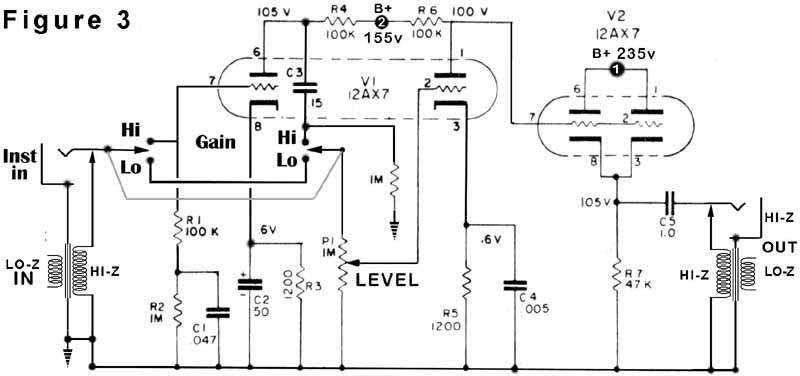
V1 and V2 are 12AX7 dual triodes. Each half of V1 is wired as a Class A voltage amplifier in a configuration known as Common Cathode. By comparison, both halves of V2 are wired together in the Cathode Follower configuration for current gain. Dont freak dudes and dudettes! Tubes are real high impedance (Hi-Z) devices just like a passive guitar or bass and, in addition to making things louder (voltage gain), they can also convert impedance in this case from high to medium (current gain). Unlike transformers, tubes and transistors can manipulate impedance without a level loss.
Remember, the outside world is a nasty place. Have you ever had an instrument cable that crackled when stepped on? That phenomenon is not an example of a bad cable so much as its the wrong cable for the application. (Its capacitance is too high and the insulation between conductors is inadequate.) The reason there are transformers at both the input and the output is to match impedance with the outside world.
Low-impedance (Lo-Z) balanced sources, such as microphones outfitted with XLR connectors, can drive long lengths of cable. The input transformer converts Lo-Z to Hi-Z and in doing so takes a small signal and steps it up to a higher albeit more vulnerable signal. (The power supply transformer manipulates voltage and current in the same way.) After the tubes do their thang, the output transformer brings the impedance down to a level thats semi-impervious to electrical interference.
INTRODUCING THE RELATIVES
While on the subject, the filament in a vacuum tube heats the cathode so that it will emit electrons, which are negatively charged. The high voltage at the plate accelerates and attracts the electrons while the grid controls electron flow. Each 12AX7 filament requires 150 milliamps (mA) so that the two in parallel draw 300mA total. By comparison, the plate current can be calculated by taking the voltage drop across any plate resistor. For example, R4 has 135vdc on one side and 105vdc on the other. The voltage drop across R4 is 30 volts, therefore, using Ohms Law, (I=V/R) the current is .3 mA with no signal applied. The filament current is 500 times that of the plate!
WHAT AND WHERE
The 1566A included 8-pin (octal) tube-style sockets into which plug-in transformers or dummy plugs were inserted for balanced or unbalanced operation, respectively. Input and output connections were via barrier strips. The intended application was as a mic amplifier for a public address system. ("Attention K-mart Shoppers!") When operated at a nominal -10 dBm (yes, please terminate into 600 ohms), the 1566A is acceptably clean. If you crank it so that the nominal level is +4 dBm, peaks will be sweetly saturating at +15dBm and asymmetrical clipping starts at about +17 dBm. Its the perfect "Electric Crayon."
Yes, you'll need Phantom Power! The good news is that I finally got 'round to writing an article for the July'97 issue of EQ Magazine. Even better (for surfing geeks), is that the heading above is the link to high-voltage love!
ENJOY
Parts Suppliers:
Jensen
TransformersAntique
Electronic SupplyCinemag New Sensor
CorporationLundahl
TransformersSowter
TransformersAltran Transformer
OverviewInput and output transformers are available from:
Jensen Transformers
(and application information)
7135 Hayvenhurst
AvenueVan Nuys, CA 91406
213-876-0059Cinemag Inc.
9050 Independence Ave.
Canoga Park, CA 91304
Tel (818) 993-4644
Fax (818) 993-4604
cinemag@sbcglobal.net
Audio Transformer Part Numbers
Manufacturer Model Application Impedance List RATIO Notes Altran C-3402-2 mic input 150/600:10k Altran Jensen jt-115k-e mic pre 150/15k $66.51 Jensen jt-10k61-1m output 11k/600 $124.28 1,4 Cinemag CMMI-10B input 150-15k 1:10 Cinemag CM-9589 output 10k-600 4:1 NOTES
- Replace C5 with at least 1.1 mF/250 vdc
- 80% nickel (lower distortion)
- 50% nickel (can handle higher output level but with increased distortion at low levels)
- The power transformer, as well as other parts, are available from http://www.tubesandmore.com
Altec 1566 Power Transformer Options
June 2011
Part Number Price NOTES CH Secondary 1 Secondary 2 Secondary 3 P-T292 $20 1 2 140 V, 100mA 28 V, 20mA 10.5v, 2A P-TF47609 $26 2 1 240V, 27mA 6.6v, 1A P-TF49967 $51 3 2 330dc, 68mA 6.6v, 2A P-T269AX $46 4 2 250vct, 100mA 6.3v, 2A F = Fender These Transformers (xfrmrs, trannies) are available at...
NOTES
When building a power supply for a vacuum tube circuit, there are many things to consider. For the Altec 1566, there is no simple answer - just many options - each with its own pluses and minuses.
- This transformer could be configured to provide all of the necessary voltages - including phantom - although the filament voltage will require regulation. No shielding, and it is a big tranny!
- OK for single channel.
- Hmmm
- Perhaps best of this lot for 2-channel, though overkill on the high voltage side.
FILAMENT POWER
Vacuum tubes require two voltage sources, one for the filament (like a light bulb) and one for the plate). The filament for the 12A?7 family can be wired in parallel (6.3v @ 300 milli-amps or mA) or in series (12.6v @ 150mA).Filament requirements:
- 4-12A?7 wired for 12v filaments @ 150mA per tube = 600mA
- use 800mA min
PLATE POWER
- 4-12A?7 wired for 6v filaments @ 300mA per tube = 1.2 amps
use 1.6 amp min
There are two triode amplifiers within each 12A?7. The plate circuit for each amplifier requires about 1mA. When you look at the power transformers above, youll see that ALL have way more current capacity than required, because most are commonly available replacements for Fender guitar amps.The rule of thumb for transformers is that they should be rated a minimum of 1.34 times the required current for safety and long life. If each plate circuit requires 1mA and there are 4 plate circuits per mic preamp, thats 8mA x 1.34 - 10.7mA. The closest xfrmr in that range is the P-TF47609 at 27mA (see image below), but it does not have ample filament current. Still, you get to see the size of it.
The other thing to consider when building your circuit is how to orient everything. Power and audio xfrmrs should not be near each other and when they must be, orientation is critical. If side-by-side, orientation should 90 degrees different so they dont talk to each other.
PHANTOM POWER
The next issue is phantom power, 48 volts DC. Neither transformer has a phantom winding, which means we have to be create and either use voltage multipliers from the low voltage filament windings or dividers from the plate windings. The P-T292 has a 28v secondary that could be voltage doubled to create 48volts.RECTIFIERS
The rectifier circuits used in the original Aletec 1566 power supply will not be appropriate for these power transformers, so it will be necessary to choose from the most suitable rectifier options. Here's a work sheet from my electronics class that shows most of the options.There are other options as well, none quite a pretty or simple as a single

Please note:
Tubes, sockets, capacitors and resistors may also be purchased through Antique Electronic Supply, New Sensor, DigiKey, Mouser and Alllied Electronics.
On both units I modified, the fuse holder was relocated to the rear panel and a quarter-inch jack was put in its place on the front panel. The 1566A does make a great active direct box and has plenty of gain. Since the front panel "Gain" control is actually a "Level" pot (and is labeled as such on the schematic) between the first and second stages, it will be ineffective if the first gain stage is overloaded.
The optional Gain switch reduces gain by eliminating the first stage, a simple solution that unfortunately does flip signal polarity. This seemed an acceptable compromise because the initial goal is to minimize circuit changes (at least the first time around) to determine the as-is character of the 1566A. Of course, there is neither room for an XLR connector (input or output) nor is there phantom power (click here for the phantom project). Readers interested in more serious mods can contact me via snail or e-mail.
With the original transformers, the first 1566A was usable and full of character. The second 1566A had problems. The power supply sagged when the output transformer was connected. I changed diodes RS-1 and RS-2 and then discovered that C5 was leaky. Rather than find transformers with octal plugs, I removed the sockets, created hardware for the new transformers and mounted them directly to the chassis. What I had "laying around," was a Jensen 115k for the input (as always, very nice) and a Sescom MI-33 which had the correct impedances, but could not handle the level at low frequencies. Just before this article went to press, I scored two of the Bauer output transformers, a significant improvement indeed!
E-mail Eddie