AE-237Week-8-9-10: Vari-Fi JFET preamp revision C
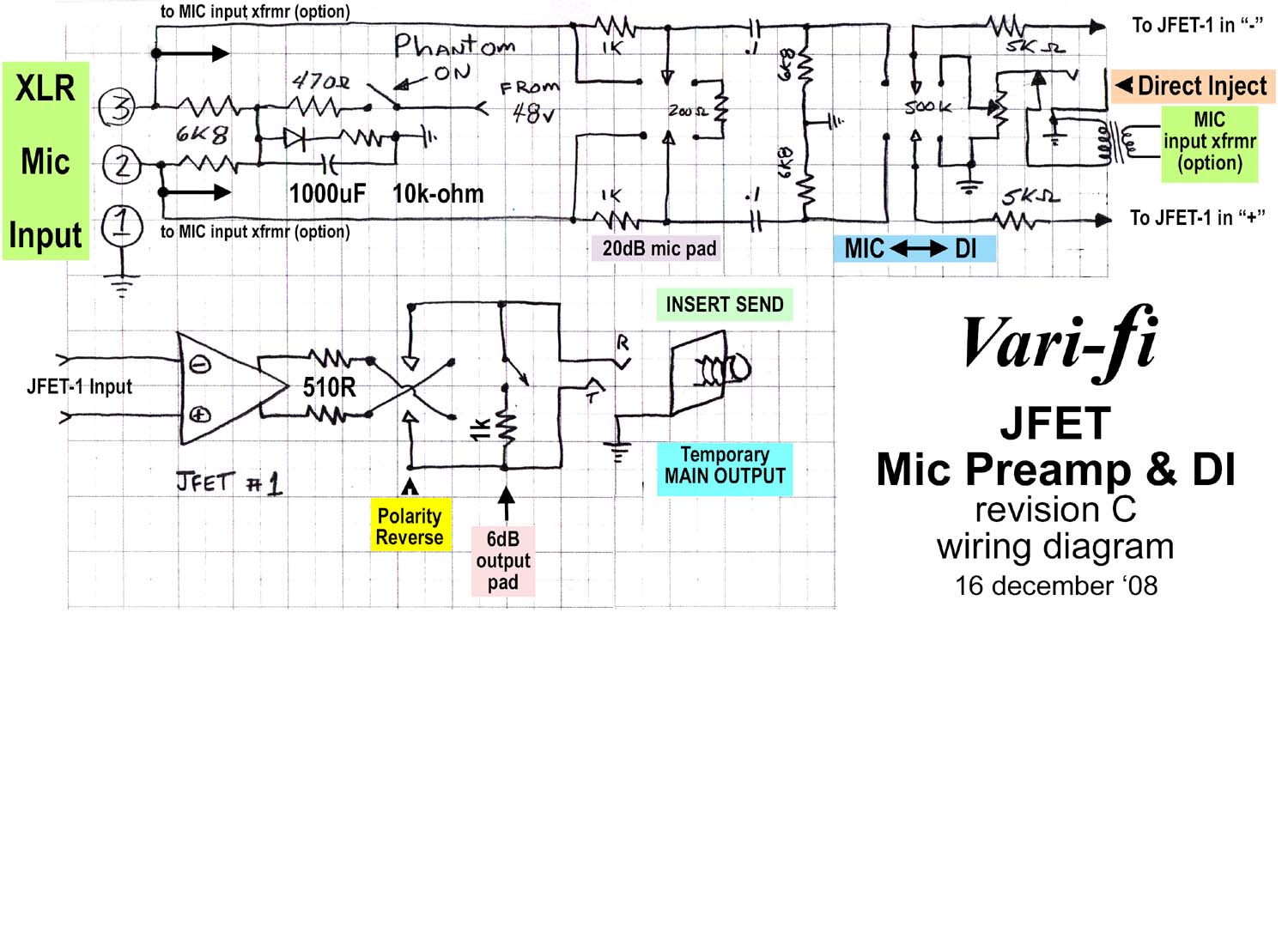
The wiring diagram for the Transformerless version of Rev C (input xfrmr included for future reference). Click on the drawing to download the higher res PDF version...
Your mission (complete and hand in on Wednesday):
- Show how the balanced output signal gets to the TRS output jack
- Explain what would be heard if headphones were plugged into this jack. Feel free to redraw in the space below the schematic.
- Use the log formula to determine how many dB the input pad will attentuate. (The fader lab might help.)
- Use the log, series and parallel resistance formulas to determine the amount a attenuation when the output pad is OUT (not engaged) and 32-ohm stereo headphones are connected.